As you know, all modern cars are equipped with direction indicators, which are a flashing light bulb or LED on the left or right side of the body. Sometimes a standard electromechanical relay fails, and getting a powerful automotive relay is not always so easy. Semiconductor devices come to the rescue - after all, building such a relay is powerful with just a couple of transistors.
Relay circuit

The circuit is an asymmetrical multivibrator; it is connected to an open circuit in series with the light bulb and the power source. When voltage is applied, the light begins to flash immediately. VT2 in the diagram is a field-effect transistor; it is through it that the entire light bulb current flows. It is preferable to use a transistor with the lowest possible open junction resistance. IRFZ44N, IRF740, IRF630 are suitable here. If a low-power LED is used instead of a light bulb, you can also use a bipolar transistor, for example, TIP122. Transistor VT1 of medium power p-n-p structure, BD140, KT814 are suitable. Diode D1 can be installed 1N4007 or 1N4148. The blinking frequency directly depends on the capacitance of the capacitors and the resistance of the resistors. To increase the frequency, you need to reduce the capacitance of capacitor C2, and to decrease the frequency, on the contrary, increase its capacitance. You can also experiment with the values of other circuit elements and observe how the duty cycle of the pulses changes.
(downloads: 456)

Circuit assembly
The entire circuit is assembled on a miniature printed circuit board measuring 35 x 20 mm; it can be manufactured using the LUT method. The tracks must be tinned after etching, then the copper will not oxidize.
First of all, resistors and a diode are soldered onto the board. After them, everything else is a pair of transistors, electrolytic capacitors and a terminal block. It is important not to confuse the pinout of the transistors and the polarity of the capacitors, otherwise the circuit will not work. When all the parts are soldered onto the board, be sure to wash off the remaining flux and check the correct installation.


Setting up and testing turn signal relays
For testing, you can connect several powerful LEDs as a load. We connect the negative of the load directly to the negative of the power supply, and connect the positive to the board. If a light bulb is used for testing, it can be connected with any polarity. We apply voltage and the light immediately begins to blink. The blinking frequency can be changed within a wide range, which is why this circuit can be found in many other applications besides being used as a turn signal relay. For example, you can use it to make a rear flashing light for a bicycle; you just need to increase the flash frequency by decreasing the capacitor capacity. The scheme can switch great power - up to several hundred watts, if you apply a field transistor designed for the corresponding current. With a power of more than 100 watts, it is advisable to install the transistor on a small radiator, otherwise it may heat up during long-term operation. Such a scheme, in contrast to the traditional electromechanical relay, does not have mobile parts, so it is much more durable if you use the details of good quality. If necessary, a fuse, indicated in the diagram as FU1, is also connected in series with the load. Happy assembly.The idea of designing a turn relay for LEDs with your own hands sooner or later comes to most car enthusiasts. The point is not that outdated devices often break down. It’s just that LEDs provide much more possibilities when indicating turns, and modification is a fairly simple task even for a novice motorist.
Replacing regular light bulbs can cause several problems, one of which is blinking too quickly. This means that the characteristics of the “native” relay are not designed to work with LEDs, and it operates in emergency mode.
Although installing LEDs to indicate turns has its own disadvantages (changes in the scattering angle, too abrupt switching on, etc.), such schemes have many advantages.
LED turn signal relays for domestic cars
Traditionally, gas and vases of the relay can be found on a motor shield located behind the dashboard. The device can be analog (231.3747) or digital (494.3747). They differ noticeably in size and can be distinguished by eye, but relays are usually marked. Refinement is only possible for the digital version, so if something happens, you need to purchase it.
The first step is to open the case. To do this, you need to put a flat screwdriver of the latch located on both sides of the lid.
Relay disassembled and the required chip (Fig. 1).
- Turn the track on the mounting board (just cut it out with the help of a blade or an office knife). To be extra safe, it is better to insulate this area with manicure varnish or any other composition. The connection goes to channel 7. This is also true for relays 495.3747.., 494.3787..., as well as for almost any other microchip-based. Alteration of the scheme for LEDs on them passes in a similar way. The only catch is to correctly determine the required channel; its location varies depending on the specific board.
- The next method has one drawback - the lack of indication of LED burnout when indicating turns (they are quite reliable, so this is not a big deal). In Fig. 1, the capacitor, which is responsible for the frequency of the generator, is highlighted in green; the modification is applied to it. So that the LEDs do not blink, but work more smoothly, this frequency must be reduced by 2 times, which means that the capacitor capacity is doubled (4.7 μF by 50 V or just add another initial face value).
- Installing additional resistors in parallel with the LEDs will also help solve the problem. The catch is only to choose the right value so that the resistance imitates the load of the lamp. On average, the resistor value is selected from the range of 2-2.5 kOhm. Remaking is much easier if you have special equipment. equipment, but the resistance value can also be selected experimentally.
- You can also solder the LEDs in series. Loads from 5 lamps should be enough to open the chain. Such turning patterns are quite common.
DIY turn relay
Refining the turn signal relay is a fascinating, but quite labor-intensive task. Sometimes it is much easier to assemble a new one, because in total only 3 parts are required. The main thing is that the connectors match.
At your nearest radio market you need to purchase:
- A powerful field transistor;
- resistor;
- flashing LED (red LEDs show best results).
Buying all 3 elements will cost only a couple of dollars.

The components are soldered directly using surface mounting.
Naturally, in daylight the power of one diode is clearly not enough. This turn relay circuit can be used to set the flicker frequency. That is, the turning relay is completely replaced, and the turn signal itself will blink.
Turners for imported cars
For the most part, foreign manufacturers have long abandoned the use of turn signals on conventional lamps. Therefore, modification of the turn relay for LEDs is required only if it is replaced or if it is planned to change the operating principle of the device.
Recently, the use of the “American” circuit of the turning relay has gained more and more popularity. It does not have the usual orange color, and the LEDs glow red during the foot and when indicating the turn.

Many people do not like this modification of signal lighting, but if you look closely, you can find such a system in action at one of the city traffic lights.
Inserting LEDs into a turn signal or changing the operating principle of an existing relay is not such a difficult task. Refining the scheme or creating a new one will not require much effort and time, but the car will be prepared for all road situations.
Annex 1.A brief overview of domestic standard relays in housings as shown in the photograph below.
Below you will find information from one manufacturer; there are other manufacturers and foreign analogues. For this part of the article, the main thing is to make it clear to the average car enthusiast that relays can be interchangeable, have different circuits, different numbers of contacts, depending on their purpose.
Domestic relays of this series mark the normally closed contact as 88. In imported relays this contact is everywhere called 87a
Typical relay circuits. Tsokolevka.
 Scheme 1 |
 Scheme 1a |
According to scheme 1, the following 5-contact (switching) relays are produced:
With 12V control - 90.3747, 75.3777, 75.3777-01, 75.3777-02, 75.3777-40, 75.3777-41, 75.3777-42
With 24Volt control - 901.3747, 901.3747-11, 905.3747, 751.3777, 751.3777-01, 751.3777-02, 751.3777-40, 751.3777-41, 751.3777-42
According to scheme 1a with an anti-interference resistor:
With 12V control - 902.3747, 906.3747, 752.101, 752.3777, 752.3777-01, 752.3777-02, 752.3777-40, 752.3777-41, 752.3777-42
With 24Volt control - 903.3747, 903.3747-01, 907.3747, 753.3777, 753.3777-01, 753.3777-02, 753.3777-40, 753.3777-41, 753.3777-42
 Scheme 2 |
 Scheme 2a |
According to scheme 2, the following 4-pin (closing/closing) relays are produced:
With 12V control - 90.3747-10, 75.3777-10, 75.3777-11, 75.3777-12, 75.3777-50, 75.3777-51, 75.3777-52, 754.3777, 754.3777-01, 754.3 777-02, 754.3777-10, 754.3777-11, 754.3777-12, 754.3777-20, 754.3777-21, 754.3777-22, 754.3777-30, 754.3777-31, 754.3777-32
With 24Volt control - 904.3747-10, 90.3747-11, 901.3747-11, 905.3747-10, 751.3777-10, 751.3777-11, 751.3777-12, 751.3777-50, 751.3777- 51, 751.3777-52, 755.3777, 755.3777-01, 755.3777-02, 755.3777-10, 755.3777-11, 755.3777-12, 755.3777-20, 755.3777-21, 755.3777-22, 755.3777-30, 755.3777-31, 755. 3777-32
According to scheme 2a with an anti-interference resistor:
With 12V control - 902.3747-10, 906.3747-10
With 24Volt control - 902.3747-11, 903.3747-11, 907.3747-10
 Scheme 3 |
 Scheme 3a |
According to scheme 3, the following 4-contact (breaking/switching) relays are produced:
With 12V control - 90-3747-20, 904-3747-20, 90-3747-21, 75.3777-20, 75.3777-202, 75.3777-21, 75.3777-22, 75.3777-60, 75.3777-602, 7 5.3777-61, 75.3777-62
With 24Volt control - 901-3747-21, 905-3747-20, 751.3777-20, 751.3777-202, 751.3777-21, 751.3777-22, 751.3777-60, 751.3777-602, 751.37 77-61, 751.3777-62
According to scheme 3a with an anti-interference resistor:
With 12Volt control - 902-3747-20, 906-3747-20, 902-3747-21, 752.3777-20, 752.3777-21, 752.3777-22, 751.3777-60, 751.3777-61, 751.3777 -62,
With 24Volt control - 903-3747-21, 907-3747-20, 753.3777-20, 753.3777-21, 753.3777-22, 753.3777-60, 753.3777-61, 753.3777-62,
ATTENTION!!!
Relays of the 19.3777 series have a housing similar to the one above. The circuit of these relays has protective and decoupling diodes. Such relays have a polarized winding. These relays are not mentioned here in the article because they have limited use.
Relays of modern cars.

Differences and variety of relay numbers mean different mountings, housing design, degree of protection, coil control voltage, switched currents and other parameters. Sometimes when choosing an analogue it is necessary to take into account some parameters.
According to scheme 5, the following 4-contact (closing/closing) relays are produced:
With 12V control - 98.3747-10, 982.3747-10
With 24V control - 981.3747-10, 983.3747-10
According to scheme 5a with an anti-interference resistor:
With 12V control - 98.3747-11, 98.3747-111, 982.3747-11
With 24V control - 981.3747-11, 983.3747-11
From time to time, questions arise with turn signal relays when they install LED lamps in the turn signals on a motorcycle, and not only on motorcycles, but also on cars, or when the turn signals themselves are replaced entirely with LED ones. Standard relays, as a rule, refuse to work with such light bulbs because the load is too small. It (the relay) perceives the LED lamp as a broken wire and begins to switch faster than usual. Under normal conditions, this is convenient: the relay began to “click” faster than usual, which means that some light bulb has burned out. But for someone who has deliberately replaced incandescent bulbs with LEDs, this is the beginning of a headache. Just a few years ago, electronic turn signal relays for LEDs cost about 500 rubles, which is not at all humane. Then I just needed a relay for the LEDs. After scouring the Internet, I found an article about converting a conventional automotive three-pin electronic turn signal relay into a relay for LEDs. I did everything, as described, everything worked, I forgot. But lately, apparently, spring is taking its toll, and the question of relays for LEDs has often come up.
For those interested, read on.
Compared to what it was a few years ago. the situation seems to have improved. So, literally today, while corresponding here with one of the forum members, who ordered himself a special turn signal relay for LEDs, I found out that the prices for these relays have dropped. According to this forum member, he ordered himself a relay for 170 rubles. Today, I bought a regular car relay at a car store for the same 170 rubles. I suppose that I could find it cheaper, because... this store is far from the cheapest, but I live in a small town, there are few stores, I stopped by another store, they ran out of relays. And I don’t see the point in going somewhere else because of winning 10-20 rubles.
So, let's move on to the alteration.
To understand what exactly and how we will redo it, here is a relay diagram:

The relay is based on a specialized integrated (on a microcircuit) pulse generator that controls the closing and opening of a small-sized relay. The microcircuit has a special pin that monitors the voltage drop across the shunt. This drop depends on the total resistance of the lamps connected (in parallel). If a lamp burns out, the resistance increases, the voltage drop across the shunt decreases, and the microcircuit begins to switch faster. If this pin of the microcircuit is turned off, it will give pulses at a constant frequency, regardless of the number and power of connected lamps, which is exactly what we need.
In the diagram, the pin that needs to be disconnected is crossed out.
Now let's move on to practical implementation.
I bought a relay like this:

A wide strip of metal is like the same shunt.
View of the board with the microcircuit:
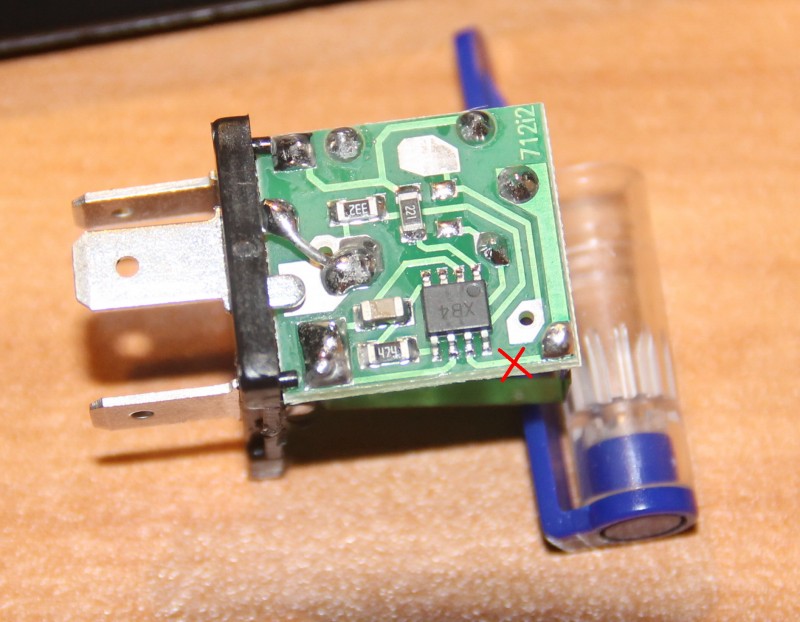
We see the microcircuit. There is a dot on her body, it is always in the corner. This point calls the key. The key is always placed at the first pin of the microcircuit. The conclusions are numbered consistently counterclockwise. If we return to the circuit, we need pin No. 7. I crossed the conductor coming from him. This is the best place to cut the conductor. If someone buys another relay, more precisely, from a different manufacturer, the internals may differ in appearance. Therefore, I explain in such detail how to find the desired conductor. I cut the track on the board with the tip of an ordinary knife, scratched it several times, saw that instead of the copper track the board was visible and that was enough. The current is scanty there, it will not break.

The incision site is circled.
I want to draw the attention of those who have a standard relapse relay. This was exactly what happened on the old Yamaha R1-Z. Don't be scared! There is simply no mass wire there.
Relay connection.
The relay has 3 outputs:
39 - ground, always connected.
49 - constant +, connected when the ignition is turned on
49a - signal, goes to the remote control for the turn switch and the emergency lights.
To connect, you need to determine where which wire is in the standard wiring. If there is a scheme, it is good, if not, you need a lamp.
First, let's find the mass. One terminal of the test lamp is on the + battery, with the other we try the wires in the connector. The turn switch and hazard lights must be turned off. Where the lamp lights up, that is the mass output. We connect the wire of the probe lamp to any ground contact and try the wires in the connector, while not forgetting to turn on the ignition. But, the lamp can light up in both wires (depending on the connection diagram of the control lamp in the tidy), so we turn on any turnover or emergency gear. The wire where the probe caught fire is the desired +. The remaining wire is the signal wire. You can check it if the wire + and the signal is closed when the turn signals or emergency rod. The turns should light up. If anyone is afraid, you can connect these 2 wires with a probe lamp, then the turn signals will light up, but dimly, and the probe is only slightly worse than when connected to the battery. And all because we turned the turn signals in series with the probe.


