The decision to replace standard light bulbs with modern LEDs has recently become of particular relevance. Thus, the presence of LEDs allows you to expand the range of color effects, as well as save on current consumption. But, despite the advantages of LEDs, there are still certain difficulties when installing them on VAZ 2110 turn signals - difficulties appear with blinking (the frequency of the signals increases sharply).
What is the reason needs to be figured out...
First of all, you need to understand the principle of operation of the VAZ 2110 turn signal relay (relay No. 3 in the fuse block), as well as other car models:
During operation of the standard light bulb in the turn signals, the plate in the relay itself heats up due to the resistance of the light bulb, therefore, the circuit opens. If the light bulb burns out, the relay does not receive enough resistance, there is no heating, there is no opening of the circuit and, as a result, frequent blinking.
Conclusion:
Rapid blinking of the direction indicators indicates the need to replace the bulb.
An identical problem appears with frequent blinking when installing LEDs in turn signals instead of bulbs, since the relay senses a lack of the necessary resistance - emergency mode is activated.
The same thing happens when replacing side lamps with diodes (the reason is still the same - relays).
Options for solving this problem:
Equipping the turn relay with an additional resistor:
- you can use the following technique - solder a resistor (approximately 2.2 kOhm) in parallel with the LEDs, which will simulate the lamp load.
– or the easiest way is to connect standard (ordinary) light bulbs in parallel with the LEDs. But this has its drawbacks: the resistors heat up and the light from the incandescent lamp deteriorates.
Increasing capacity.
In order to eliminate frequent blinking of turns with already installed LEDs, it is recommended to replace the capacitor in the turn relay. To do this, you should unsolder the old capacitor and, accordingly, solder a new one in its place (pay attention to the polarity so as not to mix it up if something happens).
Conclusion: By doubling the capacitor capacity, the number of blinks is correspondingly reduced by 2 times.
If you don’t have a larger capacitor available, you don’t need to worry: you can take a similar capacitor and solder it in parallel as an additional capacitance. Disadvantage: emergency blinking in slow motion.


LEDs for serial connection (soldering).

There is a statement that 5 LEDs soldered in a series arrangement in a turn signal create a sufficient load to open the circuit.
Open circuit in the turn relay.
One of the common methods is to open the circuit itself on the turn relay board, as a result of which the relay will operate with both standard lamps and LEDs.


The disadvantage of this option is the absence of a signal about a burnt-out turn signal.
From time to time, questions arise with turn signal relays when they install LED lamps in the turn signals on a motorcycle, and not only on motorcycles, but also on cars, or when the turn signals themselves are replaced entirely with LED ones. Standard relays, as a rule, refuse to work with such light bulbs because the load is too small. It (the relay) perceives the LED lamp as a broken wire and begins to switch faster than usual. Under normal conditions, this is convenient: the relay began to “click” faster than usual, which means that some light bulb has burned out. But for someone who has deliberately replaced incandescent bulbs with LEDs, this is the beginning of a headache. Just a few years ago, electronic turn signal relays for LEDs cost about 500 rubles, which is not at all humane. Then I just needed a relay for the LEDs. After scouring the Internet, I found an article about converting a conventional automotive three-pin electronic turn signal relay into a relay for LEDs. I did everything as described, everything worked, I forgot. But lately, apparently, spring is taking its toll, and the question of relays for LEDs has often come up.
For those interested, read on.
Compared to what it was a few years ago. the situation seems to have improved. So, literally today, while corresponding here with one of the forum members, who ordered himself a special turn signal relay for LEDs, I found out that the prices for these relays have dropped. According to this forum member, he ordered himself a relay for 170 rubles. Today, I bought a regular car relay at a car store for the same 170 rubles. I suppose that I could find it cheaper, because... this store is far from the cheapest, but I live in a small town, there are few stores, I stopped by another store, they ran out of relays. And I don’t see the point in going somewhere else because of winning 10-20 rubles.
So, let's move on to the remake.
To understand what exactly and how we will redo it, here is a relay diagram:

The relay is based on a specialized integrated (on a microcircuit) pulse generator that controls the closing and opening of a small-sized relay. The microcircuit has a special pin that monitors the voltage drop across the shunt. This drop depends on the total resistance of the lamps connected (in parallel). If a lamp burns out, the resistance increases, the voltage drop across the shunt decreases, and the microcircuit begins to switch faster. If this pin of the microcircuit is turned off, it will give pulses at a constant frequency, regardless of the number and power of connected lamps, which is exactly what we need.
In the diagram, the pin that needs to be disconnected is crossed out.
Now let's move on to practical implementation.
I bought a relay like this:

A wide strip of metal is like the same shunt.
View of the board with the microcircuit:
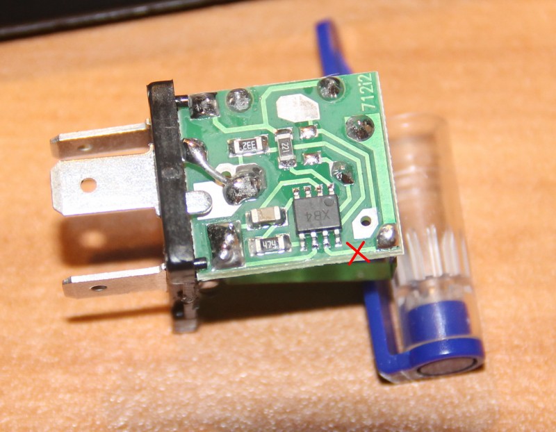
We see the microcircuit. There is a dot on her body, it is always in the corner. This point calls the key. The key is always placed at the first pin of the microcircuit. The pins are numbered sequentially counterclockwise. If we return to the circuit, we need pin No. 7. I crossed out the conductor coming from him. This is the optimal place to cut the conductor. If someone buys another relay, more precisely, from a different manufacturer, the internals may differ in appearance. That's why I explain in such detail how to find the right conductor. I cut the track on the board with the tip of an ordinary knife, scratched it several times, saw that instead of the copper track the board was visible and that was enough. The current there is scanty, it won’t break through.
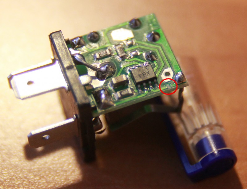
The incision site is circled.
I would like to draw the attention of those who have a standard two-contact relay. This was exactly what happened on the old Yamaha R1-Z. Don't be scared! There is simply no mass wire there.
Relay connection.
The relay has 3 outputs:
39 - ground, always connected.
49 - constant +, connected when the ignition is turned on
49a - signal, goes to the remote control for the turn switch and the emergency lights.
To connect, you need to determine which wire is which in the standard wiring. If there is a diagram, good, if not, you need a probe lamp.
First, let's find the mass. One terminal of the test lamp is on the + battery, with the other we try the wires in the connector. The turn switch and hazard lights must be turned off. Where the lamp lights up, that is the mass output. We connect the wire of the probe lamp to any ground contact and try the wires in the connector, while not forgetting to turn on the ignition. But the lamp can light up in both wires (depending on the connection diagram of the control lamp in the device), so we turn on any turn signal or emergency lights. The wire where the probe lights up is the desired +. The remaining wire is the signal wire. You can check it by shorting the + and signal wires with the turn signals or emergency lights on. The turns should light up. If anyone is afraid, you can connect these 2 wires with a probe lamp, then the turn signals will light up, but dimly, and the probe is only slightly worse than when connected to the battery. And all because we turned on the turn signals in series with the probe.
I decided to install diodes everywhere. bought relay 494.3747
but when I opened it I saw something a little different than in the first message
Using this diagram, I found the required 7th leg, which is responsible for blinking.

and broke off contact

Now I have this 3-pin relay
Using scientific poking, it was not possible to activate it. I found the diagram here
The top one is a new model, the bottom one is like what I have now.

After reading a little more, I realized that I could finally make an emergency light)))))
take the 8-pin emergency light button and start connecting:
1) Button contact 1 - To the blue wire of the steering column turn switch block. To connect the button you need to find the right three-link block, I took the wires to the button from it. connected to the block coming from the under-panel braid, and not from the three-lever.
2) Button Contact 2 - Double orange wire that used to be connected to the relay. The wire must first be extended.
3) Button contact 3 - To the blue and black wire on the steering column turn switch block.
4) Button contact 4 - To contact 1 on the relay, where the blue wire was located!
5) Contacts 5 and 6 are missing on the button!
6) Button contact 7 - Connect to contact 2 on the relay, so to speak, we double the wire with the one that is already connected there. Or on diagram L
7) Button contact 8 - constant "plus".
Another option:
the orange and blue wires are easy to recognize, but the third wire, which on the old relay is connected to the “L” contact - it can be purple or black or anything else) Next, we connect it to the contacts of the new relay:
1 contact - leave it empty, later connect it to the emergency button
Contact 2 - here we connect the wire coming from contact “L”, and another wire will go to this contact (it turns out a double wire)
Contact 3 - connect the blue wire that went to the old relay
Contact 4 - make a short wire with a round end in order to hook it onto the mounting pin of the relay itself under the nut. This is the Mass, which in the old relay was carried out using an entire housing.
1) Button contact 1 - To the blue wire of the steering column turn switch block
2) Button Contact 2 - Double orange wire that used to be connected to the relay. The wire must first be extended using a male terminal.
4) Button contact 3 - To the blue and black wire on the block of the steering column turn switch.
5) Button contact 4 - To contact 1 on the relay!
6) Contacts 5 and 6 are missing on the button!
7) Button contact 7 - Connect to contact 2 on the relay, so to speak, we double the wire with the one that is already connected there.
8) Button contact 8 is a permanent “plus”, you can take it anywhere, but the cigarette lighter is not suitable for this - why didn’t I understand... like there will be an overload when you turn on the cigarette lighter and the lamps will blink? diodes consume extremely little, so we are probably talking about a ban on ordinary light bulbs.

The areas of tuning a modern car are varied: the list includes the use of xenon lamps, installation of covers for headlights, and aerodynamic body kit...
We will focus on the practice of using LEDs in direction indicators of domestically produced cars.
Expected installation difficulties
The fashion for integrating LED lamps into cars came quickly, and significant pitfalls were immediately discovered when converting them. Regarding the turns of cars of the VAZ family (in particular the VAZ-2110), they manifest themselves in the fact that the frequency of blinking of the turn signal headlights increases.
The reasons for this phenomenon are as follows: LEDs operate at higher resistance values compared to conventional lamps. Therefore, when turned on in this way, they heat up more intensely. As a result, the plate simply heats up, as a result of which the electrical circuit opens.
When the light bulb burns out, the resistance drops sharply, causing the warning light to blink faster. You can replace a regular lamp with an LED, but this does not fundamentally change anything, so you will have to modify the turn relay for LEDs with your own hands.
Solution options
The solution to the problem is described in great detail and high quality in the video, and below we will look at all the options in more detail:
- In parallel with the LEDs, you can include a ballast resistor in the relay circuit (the choice depends on the make of the car, for a VAZ-2110, for example, it is 2.2 kOhm);
- Instead of a resistor, simply add a regular lamp in parallel;
- In the circuit, replace the capacitor with a more capacitive one;
- In parallel to the existing one, you can solder another capacitor with the same capacity.
Each option has its pros and cons. For example, if there is a ballast resistor, the electrical circuit of the turn signal relay will simply increase its power consumption, which will affect the battery life. The resistors will heat up and this will lead to a decrease in the light output of conventional lamps.
Parallel connection of another lamp is associated with difficulties in its safe installation in the same housing. By adding an additional capacitor to the circuit, you will have to come to terms with the fact that the blinking frequency of the direction indicator will significantly decrease (however, in the current rules there are no restrictions on the blinking frequency of LEDs).
Reworking the relay circuit
The number of LEDs installed in series can be determined experimentally, but in practice 5 pieces are enough: such a load is quite enough to trigger the circuit. At the same time, the circuit on the board opens, which allows it to work with both conventional and LED lamps. However, in this case, the device will not be able to signal that the turn signal bulb has burned out.
The refinement algorithm is considered using the example of a relay that operates using a U643B controller manufactured by the Chinese company Atmel. Such controllers are often used in electronic equipment circuits of modern passenger cars.
One of the functions of such a controller is to warn of a malfunction of the turn signal bulbs. The criterion for malfunction is a critical decrease in the current in the circuit, as a result of which the blinking frequency increases sharply.

Electronic turn signal relay circuit for LEDs
The operating value of the LED current is set at the output of the “Lamp failure detection” controller circuit. The nuance is that the efficiency of LED lamps is much greater than that of conventional lamps. The inconvenience is that the current consumption is reduced, and increased flickering of the LEDs is perceived by the controller as a malfunction of the turn relay.
In order to get rid of this drawback, you simply need to replace resistor R3 of the circuit with a more powerful one. This will lead to an increase in the total load, and a corresponding increase in the current strength - to values at which the turn signals will no longer blink.
An alternative solution for some car enthusiasts is to cut out the section of the circuit in the circuit that is responsible for measuring the current. However, this action also reveals a serious problem.
Since the U643B controller works with its initial parameters already set by the manufacturer, with such “tuning” of the turn signal, you can accidentally change the so-called Device Code - the controller identification code by external devices. It is impossible to reflash it. In addition, by cutting out one of the contacts in the turn signal relay circuit, you can get frequent blinking of the turn signals, which does not always satisfy the car user.
Reverse restoration will most likely not yield anything, since the relay controller has already “remembered” its new parameters and changed the Device Code.
The difficulty in adjusting the parameters of resistor R3 lies in the fact that the part works with initially small resistance values, so precise instruments will be required for adjustment, but from a technical point of view, this approach is more correct.
Limitations and procedure for modifying the turn relay
Installation of LEDs is possible only if the relays are digital. For cars of the VAZ or GAZ family, these are devices marked with the designation 494.3747 (for comparison: the designation for analog ones is 231.3747). When there is no marking, the relay class is quite simply determined by its dimensions, which are noticeably larger for the analog version. If the car only operates analog, you will have to purchase a digital one.
 Appearance of digital and analog turn relays
 The direction indicator is modified in the following sequence:
- The case is opened;
- The location of the chip responsible for the operation of the turn signals is determined: it is usually located to the right of the external board.
- The capacitor is replaced, which determines the frequency of the turn signal lamp blinking generator. The subtlety is that the capacitor capacity should be within 4.7 µF at 50 V operating voltage. Alternatively, you can install another capacitor; in most cases, the space inside the relay case allows this operation.
- Output parameters are monitored using measuring instruments. If the LEDs are functioning properly, the housing is installed in its original place.
As additional items you should purchase:
- P-channel transistor;
- A resistor from the above resistance range (if it will be soldered into the circuit and not a capacitor);
- LEDs (preferably red or orange).
Soldering of such a modernized version of the relay can be done using the usual hinged method, on top of the main circuit.
Very often people ask questions about what needs to be done so that after installing LED lamps, turns blink at normal speed.
It also happens that after installing LED lamps, the turns stop working altogether.
Let's look at two different situations.
1. After installing the LED lights, the turns work but flash too often. Moreover, the weaker the lamps, the more often they will blink.
What to do in this case:
We remove the turn signal relay and disassemble it.
We find in it a single electrolytic capacitor.
In the photo it is marked with a red rectangle.
We select its capacity so that the turns blink at normal speed.
I don’t remember exactly, but it seems to be 2.2 mkf in stock.
With my fairly powerful LED lamps, I needed to increase it approximately twice, to 4.7 microfarads.
The operating voltage of the capacitor can be any but not less than 16 and preferably 25 Volts.
2. After installing the LED lights, the turns do not flash at all.
The turn signal must be visible at all times, including during the day, in sunlight, and not just at night.
But if you think that the lamps are suitable, then we modify the relay to work with weak lamps.
On the back of the board we see a lot of things.
We need a resistor enclosed in a red rectangle.
Its nominal value at drain is 3.3 kOhm
We need to reduce it. If it is possible (and able) to replace it, then we change it to a resistor from 2 to 2.5 kOhm. In principle, it works with 3 kOhm, but I don’t know how it will be with stability.
It’s better to use 2.5 kOhm for a more reliable start.
If you are not familiar with a soldering iron, then you can take a resistor with a nominal value of about 7 ... 9.1 kOhm and simply solder it on top, parallel to the existing resistor.
After this modification, the relay begins to work with lamps from 1 W.
Naturally, you will have to select a capacitor as in the first case, to bring the blinking frequency back to normal.
But 1 W is very little power. I would even say unacceptably small for a turn signal.
If you have a relay and after this modification does not work with your lamps, then it is better to replace them with something more powerful.
It turns out that your 2 lamps (front and rear) are TOTALLY less than 1 W!
A little about LED lamps, their power and color.
The fact is that in the case of LEDs you cannot apply the same principle as with incandescent lamps. White LEDs have a very specific emission spectrum. There is little yellow in it and very little red. Therefore, a white LED placed behind, say, a red filter can lose up to 80% of the luminous flux, depending on the quality of this very filter.That is why,
See:
Here is the spectrum of a regular incandescent lamp:
You see, there is a LOT of yellow and red in it.
And there is little blue, blue and blue-green. And there's not much green either.
Precisely because the spectrum of an incandescent lamp mainly consists of yellow and red colors, it works equally well in turns behind a yellow filter and in stop lights behind a red filter.
And here is the spectrum of a white LED.
The main part of it consists of blue tones, and there is quite a bit of yellow and especially red in its spectrum.
This is precisely why LED lamps must be exactly the color behind which filter you install them.
Reds for red and yellows for yellow.
Now about the power.
A white LED is a completely different LED than color LEDs.
In a white LED, we see the glow not of the crystal itself, but of the phosphor applied on top of the crystal.
And the radiation from the crystal only excites the phosphor, causing it to emit light.
Therefore, the power of a white LED depends on two factors:
1. Crystal radiation power (phosphor excitation power)


")