The most basic generator function – battery charge battery and power supply for engine electrical equipment.
Therefore, let's take a closer look generator circuit, how to connect it correctly, and also give some tips on how to check it yourself.
Generator- a mechanism that converts mechanical energy into electrical energy. The generator has a shaft on which the pulley is planted, through which it receives rotations from the crankshaft of the engine.
A car generator is used to power electrical consumers, such as the ignition system, on-board computer, car lighting, diagnostic system, and it is also possible to charge a car battery. The power of the generator of the car is approximately 1 kW. Car generators are quite reliable in operation because they ensure uninterrupted operation of many devices in the car, and therefore the requirements for them are appropriate.
Generator device
Устройство автомобильного генератора подразумевает наличие собственного выпрямителя и регулирующей схемы. Генерирующая часть генератора с помощью неподвижной обмотки (статора) вырабатывает трёхфазный переменный ток, который далее выпрямляется серией из шести больших диодов и уже постоянный ток заряжает аккумулятор. Alternating current is induced by the rotating magnetic field of the winding (around the field winding or rotor). Next, the current is supplied to the electronic circuit through the brushes and slip rings.

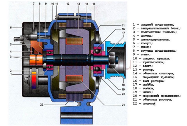
Generator structure: 1.Nut. 2. Shayba. 3.shkiv. 4.Front cover. 5. District ring. 6. Rotor. 7. Stator. 8. Powered the lid. 9.Casing. 10. Gasket. 11. Protective sleeve. 12. Rectifier unit with capacitor. 13.Latch holder with voltage regulator.
The generator is located at the front of the car engine and is started using the crankshaft. The connection diagram and operating principle of a car generator are the same for any car. There are, of course, some differences, but they are usually associated with the quality of the manufactured product, the power and the layout of the components in the motor. All modern cars are equipped with alternating current generator sets, which include not only the generator itself, but also a voltage regulator. The regulator equally distributes the current in the excitation winding, and it is due to this that the power of the generator set itself fluctuates at a time when the voltage at the power output terminals remains unchanged.
New cars are most often equipped with an electronic unit on the voltage regulator, so the on-board computer can control the amount of load on the generator set. In turn, on hybrid cars the generator performs the work of the starter-generator; a similar circuit is used in other designs of the stop-start system.
The principle of operation of a car generator

Connection diagram for the VAZ 2110-2115 generator
Generator connection diagram AC includes the following components:
- Battery.
- Generator.
- Fuse block.
- Ignition.
- Dashboard.
- Rectifier block and additional diodes.
The principle of operation is quite simple: when the ignition is turned on plus through the lock, the ignition goes through the fuse box, light bulb, diode bridge and goes through a resistor to minus. When the light on the dashboard lights up, then the plus goes to the generator (to the excitation winding), then during the process of starting the engine, the pulley begins to rotate, the armature also rotates, due to electromagnetic induction, electromotive force is generated and alternating current appears.
The most dangerous thing for the generator is the short circuit of the heat sink plates connected to the “ground” and the “+” terminal of the generator by metal objects accidentally falling between them or conductive bridges formed by contamination.
Next, the diode passes plus into the rectifier block through a sine wave into the left arm, and minus into the right arm. Additional diodes on the light bulb cut off the negatives and only positives are obtained, then it goes to the dashboard assembly, and the diode that is there allows only the negative to pass through, as a result the light goes out and the positive then goes through the resistor and goes to the negative.

The principle of operation of a car DC generator can be explained as follows: a small direct current begins to flow through the excitation winding, which is regulated by the control unit and is maintained by it at a level of slightly more than 14 V. Most generators in a car are capable of generating at least 45 amperes. The generator operates at 3000 rpm and above - if you look at the ratio of the size of the fan belts for the pulleys, it will be two or three to one in relation to the engine frequency.
To avoid this, the plates and other parts of the generator rectifier are partially or completely covered with an insulating layer. The heat sinks are combined into a monolithic design of the rectifier unit mainly by mounting plates made of insulating material, reinforced with connecting bars.
Generator connection diagram for VAZ 2107
The VAZ 2107 charging scheme depends on what type of generator is used. To recharge the battery on cars such as VAZ-2107, VAZ-2104, VAZ-2105, which have a carburetor engine, you will need a G-222 type generator or its equivalent with a maximum output current of 55A. In turn, VAZ-2107 cars with an injection engine use a generator 5142.3771 or its prototype, which is called a high-energy generator, with a maximum output current of 80-90A. It is also possible to install more powerful generators with an output current of up to 100A. Absolutely all types of alternating current generators have built-in rectifier units and voltage regulators; they are usually made in the same housing with brushes or are removable and mounted on the housing itself.
The VAZ 2107 charging circuit has minor differences depending on the year of manufacture of the car. The most important difference is the presence or absence of a charge indicator lamp, which is located on the instrument panel, as well as the method of connecting it and the presence or absence of a voltmeter. Such circuits are mainly used on carburetor cars, while on cars with injection engines the circuit does not change; it is identical to those cars that were manufactured previously.
Generator set designations:
- “Plus” of the power rectifier: “+”, V, 30, V+, WAT.
- “Ground”: “-”, D-, 31, B-, M, E, GRD.
- Excitation winding output: Ш, 67, DF, F, EXC, E, FLD.
- Output for connecting to the serviceability lamp: D, D+, 61, L, WL, IND.
- Phase output: ~, W, R, STA.
- Output of the stator winding zero point: 0, MP.
- Output of the voltage regulator for connecting it to the on-board network, usually to the “+” of the battery: B, 15, S.
- Voltage regulator output for powering it from the ignition switch: IG.
- Voltage regulator output for connecting it to the on-board computer: FR, F.

Generator circuit VAZ-2107 type 37.3701
- Accumulator battery.
- Generator.
- Voltage regulator.
- Mounting block.
- Ignition switch.
- Voltmeter.
- Battery charge indicator lamp.
When the ignition is turned on, the plus from the lock goes to fuse No. 10, and then goes to the battery charge indicator lamp relay, then goes to the contact and to the coil output. The second terminal of the coil interacts with the central terminal of the starter, where all three windings are connected. If the relay contacts close, then the control lamp lights up. When the engine starts, the generator generates current and an alternating voltage of 7V appears on the windings. A current passes through the relay coil and the armature begins to attract, and the contacts open. Generator No. 15 passes current through fuse No. 9. Similarly, the excitation winding receives power through the brush voltage generator.
Charging diagram for VAZ with injection engines
This scheme is identical to the schemes on other VAZ models. It differs from the previous ones in the method of exciting and monitoring the serviceability of the generator. It can be carried out using a special control lamp and a voltmeter on the instrument panel. Also, through the charge lamp, the generator is initially excited at the moment it starts working. During operation, the generator operates “anonymously,” that is, excitation comes directly from pin 30. When the ignition is turned on, power through fuse No. 10 goes to the charging lamp in the instrument panel. Then it goes through the mounting block to pin 61. Three additional diodes provide power to the voltage regulator, which in turn transmits it to the excitation winding of the generator. In this case, the indicator lamp will light up. It is at that moment when the generator operates on the plates of the rectifier bridge that the voltage will be much higher than that of the battery. In this case, the control lamp will not light up, because the voltage on its side on the additional diodes will be lower than on the side of the stator winding and the diodes will close. If the control lamp lights up while the generator is running, this may mean that additional diodes are broken.
Checking generator operation
There are several ways to use certain methods, for example: you can check the output current of the generator, the voltage drop on the wire that connects the current output of the generator to the battery, or check the regulated voltage.
To check, you will need a multimeter, a car battery and a lamp with soldered wires, wires for connecting between the generator and the battery, and you can also take a drill with a suitable head, since you may have to twist the rotor by the nut on the pulley.
Basic check with a light bulb and multimeter
Connection diagram: output terminal (B+) and rotor (D+). The lamp must be connected between the main output of the generator B+ and contact D+. After this, we take the power wires and connect the “minus” to the negative terminal of the battery and to the generator ground, the “plus”, respectively, to the plus of the generator and to the B+ output of the generator. We fix it on a vice and connect it.
“Ground” must be connected very last so as not to short-circuit the battery.
We turn on the tester in DC mode, attach one probe to the battery to “plus”, and the second one too, but to “minus”. Next, if everything is in working order, then the light should light up, the voltage in this case will be 12.4V. Then we take a drill and start turning the generator, accordingly, the light bulb will stop burning at this moment, and the voltage will already be 14.9V. Then we add a load, take an H4 hologen lamp and hang it on the battery terminal, it should light up. Then we connect the drill in the same order and the voltage on the voltmeter will show 13.9V. In passive mode, the battery under the light bulb gives 12.2V, and when we turn it with a drill, it gives 13.9V.

Generator test circuit
- Check the functionality of the generator by short circuit, that is, “to spark”.
- It is also undesirable to allow the generator to operate without consumers turned on; it is also undesirable to operate with the battery disconnected.
- Connect terminal “30” (in some cases B+) to ground or terminal “67” (in some cases D+).
- Carry out welding work on the car body with the generator and battery wires connected.
Depending on the year of manufacture of the car, the connection diagram for the VAZ-2107 generator may vary. Over the years, various devices have been added to the car, and electricity consumption has increased. If in the early 80s you could find a radio or (in very rare cases) a cassette recorder on cars, today the list is supplemented by central locks, alarm and security systems, and acoustics (subwoofers, powerful amplifiers).
Various types of devices help the driver - video recorders, navigators, inverters, chargers, pumps, etc. And they all consume electricity, and a generator helps replenish the charge, which charges the battery to the optimal level.
Carburetor engines
The connection diagram for the VAZ-2107 generator (carburetor and injector) depends on the year of manufacture of the car. The first carburetor models had a G-222 generator installed. The same device can be found on commercially produced VAZ-2105 and VAZ-2104 models with a carburetor injection system.
The maximum output current for such an installation is 55 amperes. But in recent years, cars with fuel injection systems have become widespread. Its use implies a large current consumption, so it is necessary to use a generator with a high current to ensure a normal charge level and power supply to all consumers.
Injection engines

On injection engines, generator sets 5142.3771 or similar are used. They have increased energy, the maximum current is about 80-90 A, it all depends on the design option. Cars of the seventh series and similar models are good because they are like a designer set. You can install almost any generator on them, similar in design to the “native” one.
For tuning, installations with an output current of 100 amperes and higher are used. But the use of such devices is justified only if many powerful consumers are connected to the electrical equipment. Regardless of the design, the generators produce alternating current; a voltage regulator, capacitor and diode block are installed in the housing.
Cars before 1986

The G-222 generator was used in cars. The connection diagram for the VAZ-2107 is almost the same as on later models. But there are features, among the main ones - there is a control lamp indicating battery charging. Moreover, it worked using an electromagnetic relay.
When the ignition is turned on, power is supplied from the lock through the instrument panel fuse to the electromagnetic relay of the battery charge lamp and the coil contact. The second contact of the coil is connected to the center wire on the generator (the point where the three windings connect).
The electromagnetic relay has normally closed contacts, so when the ignition is turned on, the lamp lights up. But as soon as the engine starts running, the generator produces current. And a current flows through the control lamp coil, which causes the armature to attract and open the contacts.
At the same time, the power to the incandescent lamp stops and it goes out. This indicates that the battery is charging normally. Only when the power supply to the lamp stops will voltage be applied to the excitation winding and the generator will be able to return to operating mode.
Cars manufactured in 1996 and later (carburetor engines)
The connection diagram for the G222 generator on a VAZ-2107 after 1996 differs from the previous one in one small feature - the power supply to the excitation winding has been changed. Cars have been improved, and some improvements make it possible to kill two birds with one stone - simplify the design and make the fate of the driver easier.
After 1996, instead of a warning lamp, they began to install a voltmeter, which more or less accurately shows the battery charge level. And if the lamp allows you to monitor only the presence or absence of voltage on the generator, then using a voltmeter the driver visually assesses the level. And if necessary, it can understand that repairs or maintenance are necessary.
Generator circuit for injection engines

In fact, the design of the generator set is not much different from those installed on carburetor engines. Only the type of excitation and serviceability monitoring differ. The dashboard contains not only a warning lamp, but also a voltmeter; these two devices allow you to assess both the presence and level of charging. Current flows through the lamp filament and is supplied to the field winding when the engine starts. The connection diagram for the VAZ-2107 generator, regardless of the year of manufacture, implies operation in the following mode:
- When the ignition is turned on, power is supplied to the excitation winding. A magnetic field appears around the armature.
- When the crankshaft rotates with the starter, the generator armature also begins to move. With the help of movement and a magnetic field, a potential difference arises at the ends of the stator windings.
- From the windings, voltage (alternating, three-phase) is supplied to the rectifier block, and from it to terminal “30” of the generator.
- Pin “30” is connected to the battery (positive terminal). Consequently, the entire electrical system is powered and the battery is charged.
In this case, the battery and generator G221A work in parallel. The connection diagram for the VAZ-2107 with carburetor and injection engines is almost identical, with only minor features.
Conclusion

If a control lamp is provided, then current will flow through it, regardless of whether the generator or battery powers the power supply system, they work in pairs. But if there is a break in the excitation winding, the brushes are worn out, then the lamp will not go out, since the generator will not be able to reach normal operating mode and provide power to all consumers. The connection diagram for the VAZ-2107 generator does not have any other features.
An almost similar one is used on all cars (and not only those produced by AvtoVAZ, but also from other factories). The power supply circuit for the excitation winding is standard; the laws of electrodynamics are the same everywhere. Without power to the rotor winding, it will not be possible to remove voltage from the stator terminals, since there will be no rotating magnetic field.
Many motorists are interested in how to excite a generator without using a battery. This may be necessary for those motorists who often travel long distances, and the battery will last no more than 2 hours without recharging the car. Let's figure out how to do this.
Basic information about the excitation effect
ATTENTION! A completely simple way to reduce fuel consumption has been found! Don't believe me? An auto mechanic with 15 years of experience also didn’t believe it until he tried it. And now he saves 35,000 rubles a year on gasoline!
As is known, the voltage generated by the gene at different engine speeds is regulated by excitation windings. The current is maintained at a constant voltage - 13.8-14.2 V.
To provide the automotive system (numerous consumers) with current, a regulator or LV is provided. It can be found on domestic cars and some foreign cars; as a rule, it is built inside the generator. In everyday life, such a regulator is called a chocolate bar, a tablet, etc.
The gene is connected to the positive terminal of the battery through terminal “30”. It is also called plus, "B" or "BAT". As for the negative output, it is designated as “31” or minus. Also in everyday life there are other designations: “D”, “B-”, etc. The tablet terminal used to supply power from the vehicle network when the ignition is on - terminal “15” or “S”. Finally, the terminal designed to supply current to the charging test lamp is designated “61” or “D+”.

If the battery stops charging, this in most cases indicates damage to the chocolate bar. However, you shouldn’t despair here, because it will be enough to apply voltage to the windings, that is, to excite the generator in order to get to the store or the nearest service station.
So, in order to get to the right place without subjecting the battery to a deep discharge, you need to remove the chocolate bar and excite the gene.
Generator circuit
The question arises, how to connect the generator? In order to be able to excite a gene without using a battery, it is recommended to carefully study the scheme and principle of functioning of genes of various modifications.
It is also important to understand why the gene is needed and what it does specifically. In other words, a gene is an electric machine that converts mechanical energy into electric current. Thanks to the gene, the battery is charged back and all electrical consumers in the operating position are supplied with current.
The gene is located at the front of the engine and is driven by the crank shaft. On hybrid cars, the gene performs the work of the starter. It is noteworthy that the same pattern is observed in some “full-fledged” cars equipped with a stop-start design.
It becomes clear that automobile genes can have two schemes, two constructive types. Their difference lies in the difference in the layout of the fan, rectifier unit and drive pulley. Also, generators with different circuits differ in geometric dimensions.
The general parameters of both types of generators remain unchanged. Any gene must include a rotor or inductor, stator and other parts.
Let's consider the circuit of a self-generator of the domestic “classic”. This gene was installed on almost all models of old domestic cars.

 Now let's look at another scheme, more modern. In particular, it is used on the V8 and other VAZ cars.

 And this is a diagram of how the gene is connected and, in fact, how it functions.

The main function of the gene rotor is to create a magnetic field. For this purpose, there is a winding or VO (exciter) on the shaft. The VO is located on the beaks or protrusions of the pole halves. The shaft also has a contact group consisting of 2 copper rings. The voltage goes through them to the VO. The rings are soldered to the VO terminals.
Note. Quite rarely, but still, not copper, but steel or brass rings can be found.
In addition, a place was found on the rotor shaft for fan impellers (the number of them depends on the design of the model). The VPD (drive pulley) is fixed in the same place.
Another rotor component is bearings.
As for the stator, it performs the function of creating alternating voltage. The core and winding found a place in it. The metal core is assembled from plates.

There are 36 slots in the stator, which are used for laying the winding. In total, it turns out to install three windings, thereby providing a 3-phase connection.
It is interesting that the windings are placed in the recesses in two ways - in a wave or in a loop. And the windings are interconnected either according to the “asterisk” or “triangle” circuit.

A rectifier unit or VB is needed to adjust the current values produced by the gene. It converts sinusoidal current into direct current in the vehicle's on-board network.
VB are simply plates, tracks that effectively remove heat. They have diodes installed in them. The VB contains 6 power semiconductor diodes. There are two diodes for each phase, naturally, one for the plus and the other for the minus terminal of the gene.
Brushes are a unit that provides current transmission to slip rings. The brush assembly consists of graphite elements, the brushes themselves, pressure springs and a holder. In modern type genes, the brush assembly creates a single block together with the regulator (chocolate).
The tablet is designed to maintain the gene current at certain values. Modern regulators are electronic (single) or hybrid. If a hybrid design is in use, then radio components and electrical appliances are introduced into the circuit, if integral (single) - all elements are made using TMT (microelectronics).
The generator drive operates by rotating a belt drive. Thus, it provides the inductor with the rotation speed that is necessary (it, as is known, must exceed the rotation speed of the crank shaft several times).
So, on most gene models, the VO is connected through a separate group consisting of 2 diodes. The latter are also called rectifiers; they prevent the passage of battery discharge voltage when the internal combustion engine is stationary.
Note. If the windings are connected in a star circuit, then 2 additional power-type diodes are placed at the zero terminal, which allows you to increase the power of the gene by as much as 15%. The VB is mounted into the gene circuit by electrical soldering or mechanical fixation.
The regulator or tablet in the generator is the most important thing. It is she who is responsible for stabilizing the voltage. And this, as you know, is very necessary when changing the rotation speed of the crank shaft and internal combustion engine. Stabilization with chocolate is carried out automatically, by influencing the VO. Thus, the tablet controls both the frequency of the voltage signals and the duration of the pulses.
Interesting point. The tablet changes the current used to charge the battery due to temperature compensation of voltage. In other words, the warmer it gets, the less current flows to the battery.
How to excite a gene
So, what needs to be done to excite the generator? As mentioned above, the tablet should be removed from the generator, since the malfunction arose precisely there. Next, connect the positive terminals of both devices, and cut the negative terminal in the chocolate bar. During the assembly process, connect it to a mass of brushes.
Insulate the wire from terminal “30” of the gene, connect an indicator with a power of no more than 15 W to the output circuit “15”. This applies to the genes of the G222 series. If the units are of other models, then they must be excited by connecting the indicator to terminal “B”.
Self-excitation of a generator can be imagined this way.

In the diagram above, the leftmost arrows indicate diodes. They are installed only in generators of modern models; they do not exist in older units. More precisely, the circuit without the presented diodes is considered classic, and with them - modernized, modern.
In some gene models, the anchors imply the presence of brushes. They are also removed and the tablet is drilled out. One contact goes directly to the armature through the diodes to the plus, as can be seen in the diagram, the second contact goes to the minus (lowest arrow).
Accordingly, the diagram shows: plus and minus.
The current will not begin to flow immediately, that is, not at low speeds. Somewhere, if you look at the tachometer, voltage will begin to be generated after 4000 rpm. In other words, we rev up to 4 thousand rpm and current appears. If we go down to 1 thousand rpm or less, the voltage disappears and we will need to rev the throttle again. This is approximately the principle of current generation during self-excitation.
Some cars have a low-speed engine. In this case, you will have to do something with the pulleys to increase the initial rotation speed. For a normal engine everything should be fine.

Go ahead. The output is not 12 volts, you should know this from the beginning. Without a regulator, the gene will output whatever it can, up to 20-30 volts. For example, during start it reaches 36 volts. This can be checked by using a light bulb of this voltage connected to the outputs. Then it drops to 20 volts.
The scheme can certainly be improved. For example, embed a capacitor into the positive wire going to the armature. This is done in order to prevent a drop in voltage when the engine speed drops. A good capacitor can also be placed at the output to smooth out the first voltage surge and regulate and smooth out dips.
When implementing this circuit, it is important to remember about delivering high voltage. This is not 12 volts, you can easily burn out light bulbs, the ECU and basically all the car electrics.
Warning. In self-excitation mode, the gene will give everything it can without any restrictions, which is fraught with overheating for itself. A little more load, and write a eulogy to the generating device. Therefore, this method is applicable only as a necessary measure, again, if you are left on the road and need to get to the nearest service station.
An electrical machine that converts mechanical energy into electrical current is called a car generator. The function of a generator that it performs in a car is to charge the battery and power electrical equipment when the engine is in working condition. An alternator serves as a car generator.
The generator is located in the engine most often in its front part, driven from the crankshaft. On hybrid cars, the generator performs the work of the starter-generator, and a similar circuit is used in some other stop-start system designs. Currently, Denso, Delphe and Bosch rank first in the world in the production of generators.
There are two types of designs of car generators: compact and traditional. The differences that characterize these types consist of differences in the fan layout, different housing design, rectifier unit and drive pulley, and geometric dimensions. The general parameters available in both types of car generators are:
- Rotor;
- Stator;
- Frame;
- Voltage regulator;
- Rectifier block;
- Brush unit.

| 1 – clamping sleeve | 14 – pin “67” |
| 2 – bushing | 15 – neutral wire plug |
| 3 – buffer sleeve | 16 – generator mounting stud |
| 4 – back cover | 17 – fan impeller |
| 5 – screw for fastening the rectifier unit | 18 – pulley |
| 6 – rectifier block | 19 – plates |
| 7 – valve (diode) | 20 – ring |
| 8 – rear bearing | 21 – front bearing |
| 9 – slip rings | 22 – rotor winding |
| 10 – rotor shaft | 23 – rotor |
| 11 – brushes | 24 – stator winding |
| 12 – pin “30” | 25 – stator |
| 13 – brush holder | 26 – front cover |

| 1 – casing | 17 – pulley |
| 2 – terminal “B+” for connecting consumers | 18 – nut |
| 3 – noise suppression capacitor 2.2 µF | 19 – rotor shaft |
| 4 – common terminal of additional diodes (connected to the “D+” terminal of the voltage regulator) | 20 – front rotor shaft bearing |
| 5 – holder of positive diodes of the rectifier unit | 21 – beak-shaped rotor pole pieces |
| 6 – holder of negative diodes of the rectifier unit | 22 – rotor winding |
| 7 – stator winding terminals | 23 – bushing |
| 8 – voltage regulator | 24 – tightening screw |
| 9 – brush holder | 25 – rear rotor bearing |
| 10 – back cover | 26 – bearing sleeve |
| 11 – front cover | 27 – slip rings |
| 12 – stator core | 28 – negative diode |
| 13 – stator winding | 29 – positive diode |
| 14 – spacer ring | 30 – additional diode |
| 15 – washer | 31 – pin “D” (common pin of additional diodes) |
| 16 – cone washer |

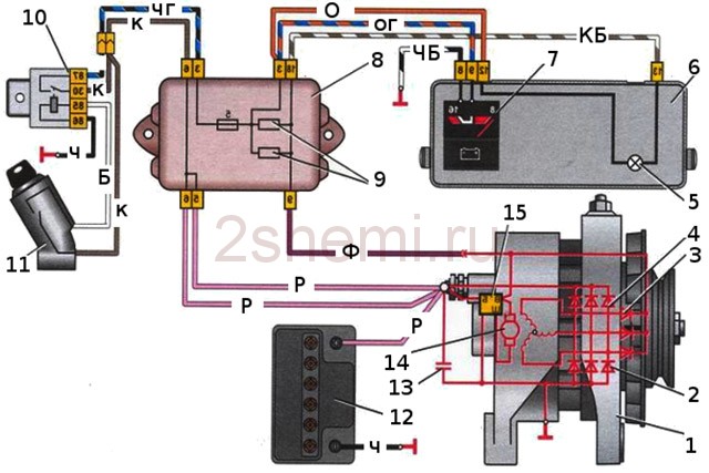
1 - generator; 2 - negative diode; 3 - additional diode; 4 - positive diode; 5 - indicator lamp for battery discharge; 6 - instrument cluster; 7 - voltmeter; 8 - mounting block; 9 - additional resistors 100 Ohm, 2 W; 10 - ignition relay; 11 - ignition switch; 12 - battery; 13 - capacitor; 14 - rotor winding; 15 - voltage regulator
The main task of the rotor– create a rotating magnetic field; for this purpose, the excitation winding is located on the rotor shaft. It is placed in two pole halves, each pole half has six projections - they are called beaks. There are also slip rings on the shaft, two of them, and it is through them that the excitation winding is powered. Rings are most often made of copper; steel or brass rings are quite rare. The excitation winding leads are soldered directly to the rings.
One or two fan impellers are placed on the rotor shaft (their number depends on the design) and a driven drive pulley is fixed. Two maintenance-free ball bearings make up the rotor bearing unit. A roller bearing can also be located on the slip ring side of the shaft.
The stator is necessary to create an alternating electric current; it combines a metal core and windings, the core is made up of plates, they are made of steel. It has 36 grooves for winding windings, windings are laid in these grooves, there are three of them, they form a three-phase connection. There are two ways to lay windings in grooves - the wave method and the loop method. The windings are connected to each other using star and delta circuits.
What are these diagrams?
- “Star” - some ends of the windings are connected at one point, and the other ends are the conclusions;
- “Triangle” is a circular connection of the ends of the windings in sequence, the conclusions come from the connection points.
The brush assembly serves to ensure the transfer of excitation current to the contact rings. It consists of two graphite brushes, springs that press them, and a brush holder. In generators of modern machines, the brush holder is located with the voltage regulator in a single non-separable unit.
The rectifier unit performs the function of converting the sinusoidal voltage generated by the generator into the DC voltage of the vehicle's on-board network. These are plates that act as heat sinks, with mounted diodes. The block contains six power semiconductor diodes, for each phase there are two diodes, one for the “positive” and the other for the “negative” terminal of the generator.
On many generators, the excitation winding is connected through a separate group, which consists of two diodes. These rectifiers prevent battery discharge current from passing through the winding when the engine is not running. When the windings are connected according to the star principle, two additional power diodes are installed at the zero terminal, allowing the generator power to be increased by up to 15 percent. The rectifier unit is connected to the generator circuit at special mounting sites by soldering, welding, or bolting.
Voltage regulator– its purpose is to maintain the generator voltage within certain limits. Currently, generators are equipped with semiconductor electronic (or integrated) voltage regulators.
Voltage regulator designs:
- hybrid design - the use of radioelements and electronic devices in an electronic circuit together;
- integral design - all components of the regulator (not counting the output stage) are made using thin-film microelectronic technology.
The voltage regulator changes the voltage supplied to charge the battery by thermally compensating the voltage (depending on the temperature of the air). The higher the air temperature, the less voltage goes to the battery.
The generator is driven by a belt drive and ensures rotation of the rotor at a speed exceeding the crankshaft speed by two to three times. In different generator designs, a poly-V-ribbed or V-belt can be used:
- V-belt has the prerequisites for rapid wear (this depends on the specific diameter of the pulley) since the scope of application of the V-belt is limited by the size of the driven pulley.
- V-ribbed belt It is considered more universal, applicable for small diameters of the driven pulley, and with its help a larger gear ratio is realized. Modern generator models have a poly-V-belt in their designs.

When the key is turned in the ignition switch, current is supplied to the field winding through the brush assembly and slip rings. A magnetic field is induced in the winding. The generator rotor begins to move with the rotation of the crankshaft. The stator windings are penetrated by the magnetic field of the rotor. An alternating voltage appears at the terminals of the stator windings. Upon reaching a certain rotation speed, the excitation winding is powered directly from the generator, that is, the generator goes into self-excitation mode.
The alternating voltage is converted by the rectifier unit into direct voltage. In this state, the generator provides the required current to charge the power supply to consumers and the battery.
The voltage regulator comes into operation when the load and crankshaft speed change. He regulates the switching time of the excitation winding. The switching time of the field winding decreases as the external load decreases and the generator speed increases. The time increases as the load increases and the rotation speed decreases. When the current consumed exceeds the generator's capabilities, the battery is switched on. There is a warning lamp on the instrument panel that monitors the operating condition of the generator.
Main parameters of the generator:
- Rated voltage;
- rated excitation frequency;
- rated current;
- self-excitation frequency;
- Efficiency (coefficient of efficiency).
Current-speed characteristic– this is the dependence of the current on the generator speed.
In addition to the nominal values, the current-speed characteristic has other points:
- minimum current and minimum operating speed (40-50% of the rated current is the minimum current);
- maximum current and maximum rotation speed (maximum current is no more than 10% higher than the rated current).
Video
The generator in cars is designed to generate electricity and charge the battery. If the normal operation of a car electric generator is disrupted, the battery begins to discharge and soon the car will stop starting completely - there is not enough battery charge. This device consists of a three-phase diode bridge, which, in turn, has 6 silicon diodes. Electrical voltage is created by the excitation of the rectifier at the moment when the rotor poles change under the stator windings. When the rotor rotates inside the machine stator, the poles of the rotor change. To increase the value of magnetic fluxes, the stator contains an electromagnetic exciting winding in the area of the magnetic cores. Marking and designation of wires:
- P - pink.
- F - purple.
- O - orange.
- B&W - black and white.
- KB - brown and white.
- CHG - black and blue.
- K - brown.
- H - black.
- B - white.
Connection diagram for the VAZ-2101 generator

Structurally, generator 2101 consists of the following main elements:
- Rotor– the moving part rotates from the engine crankshaft. Has an excitation winding.
- Stator– the stationary part of the generator, also has a winding.
- Front and back covers, inside which bearings are installed. They have eyelets for attaching to the internal combustion engine. The back cover contains a capacitor necessary to cut off the alternating current component.
- Semiconductor bridge– called a “horseshoe” for its similarity. Three pairs of semiconductor power diodes are mounted on a horseshoe-shaped base.
- Pulley, onto which the VAZ-2101 generator belt is put on. The belt is V-shaped (on modern cars a multi-ribbed belt is used).
- Voltage regulator installed in the engine compartment, away from the generator. But still it must be considered part of the structure.
- Brushes mounted inside the generator and transmit the supply voltage to the excitation winding (on the rotor).
Connection diagram for the VAZ-2106 generator

Connection diagram for the VAZ-2107 generator

1 - battery; 2 - negative diode; 3 - additional diode; 4 - generator; 5 - positive diode; 6 - stator winding; 7 - voltage regulator; 8 - rotor winding; 9 - capacitor for suppressing radio interference; 10 - mounting block; 11 - battery charge indicator lamp in the instrument cluster; 12 - voltmeter; 13 - ignition relay; 14 - ignition switch.
Connection diagram for the VAZ-2108 generator

The VAZ-2108 generator has a rather massive stator winding, since it uses a large cross-section wire. It is with its help that electricity is generated. The wire is wound evenly over the entire inner surface of the stator into recesses specially provided for this purpose in the magnetic core. It’s worth talking about the latter separately. The middle part, the generator stator, consists of a series of thin metal plates pressed tightly together. They are often boiled on the outside to prevent separation.
Connection diagram for the VAZ-2109 generator
- Alternator. The 37.3701 or 94.3701 series can be installed.
- Negative diode.
- Additional diode.
- Positive diode.
- Alternator warning lamp, also known as battery discharge lamp.
- Instrument cluster.
- Voltmeter.
- Relay and fuse box located in the engine compartment in the compartment between the engine and the vehicle interior.
- Additional resistors built into the fuse mounting block.
- Ignition relay.
- Egnition lock.
- Accumulator battery.
- Capacitor.
- Rotor winding.
- The voltage relay is located in the engine compartment.
Connection diagram for the VAZ-2110 generator
On VAZ-2110, 2111 and 2112 cars, a 94.3701 generator was installed with a maximum output current of 80 Amperes and a voltage = 13.2–14.7 Volts.

Here is the transcript generator connection diagrams on ten:
- Battery 12V;
- generator 94.3701;
- mounting block;
- egnition lock;
- battery charge indicator lamp in the instrument cluster
How to check the generator yourself
How to check a VAZ generator using the example of model 2109. Generator type 94.3701 alternating current, three-phase, with a built-in rectifier unit and an electronic voltage regulator, right-hand rotation.

Generator connection diagram. The voltage to excite the generator when the ignition is turned on is supplied to terminal “D+” of the regulator (terminal “D” of the generator) through indicator lamp 4 located in the instrument cluster. After starting the engine, the excitation winding is powered by three additional diodes installed on the generator rectifier block. The operation of the generator is controlled by a warning lamp in the instrument cluster. When the ignition is turned on, the lamp should be on, and after starting the engine, it should go out if the generator is working. If the lamp is brightly lit or glows half-lit, it indicates a malfunction.
The “minus” of the battery should always be connected to ground, and the “plus” should always be connected to the “B+” terminal of the generator. Failure to turn the battery back on will immediately cause increased current through the generator valves and damage them.
It is not allowed to operate the generator with the battery disconnected. This will cause short-term overvoltages to occur at the “B+” terminal of the generator, which can damage the generator voltage regulator and electronic devices in the vehicle’s on-board network.
It is prohibited to check the functionality of the generator “for spark” even by briefly connecting the “B+” terminal of the generator to ground. In this case, significant current flows through the valves and they are damaged.
Replacement and removal of the electric generator
The generator on a VAZ car is removed either for complete replacement in case of failure or to carry out repair work to replace faulty parts. To perform dismantling, prepare a standard set of tools; it is advisable to drive the car into the inspection hole.


- Disconnect the battery.
- Remove the protective rubber cap from terminal “30” and unscrew the nut and remove it from the wire stud.
- Disconnect the block with wires from the generator connector.
- We loosen the tightening of the generator fastening to the adjusting bar, after which
lift it all the way up to the cylinder block and remove the belt from the pulleys. - Completely unscrew the bolt securing the adjusting bar to the cylinder block, then from the bottom of the car unscrew the 2 bolts securing the lower bracket to the block and remove the generator, pulling it out of the engine compartment.